BOM Manager
BOM Manager
Organize and manage material items prior to Bill of Material report generation. Tools in this interface allow you to group material items into user defined BOM Documents. Each BOM Document includes material items for a specific region or area within the Substation. Each revision for a BOM Document has a direct relationship to a Work Order. This relationship enables Work Order and BOM Document pull-down report filters when generating reports. BOM Manager also provides the capability to add additional items to your Bill of Material without having to physically place an object in a model or drawing. The interface also provides the ability to add custom parts. (Also known as Non-Coded Parts) Structures and foundations designed specifically for a Substation site are considered typical Non-Coded Parts. Sometimes these items appear on bills of materials without having a Part Numbers or Stock Codes. You can utilize Custom Parts feature to reduce Parts Database maintenance as you are not required to create a part number record. However, it is possible to create a generic Non-Coded part number which can be used as an item template.
Typical Workflow
- Use
Properties Control to assign Work Order to objects placed in
drawings and models.
- Load Data into BOM
Manager
- Create or Select
existing BOM Document. Refer to
Add New BOM Dialog for creation details.
- Create or Select BOM Document Revision (Optional Step) Refer to Add New Revision Dialog for creation details.
- Create or Select
existing BOM Document. Refer to
Add New BOM Dialog for creation details.
- Load Data into BOM
Manager
Accessed from:
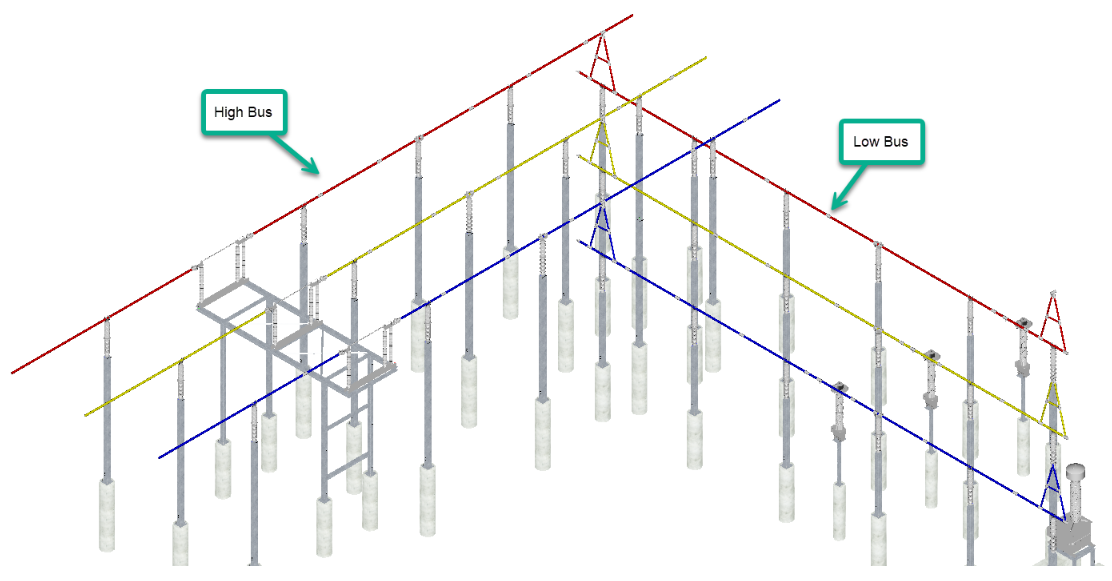
BOM Document concept/example. Say you need two separate Bill of Material reports (documents) generated from below model. One material report for only items associated to High Bus, the other for Low Bus. In this case, you can create two separate BOM Documents using Add New > Bill of Material (BOM). One named High Bus BOM, the other Low Bus BOM.
Load Data
- By BOM Document: Loads data into the tree by selecting BOM documents from the Load BOM Data by Document dialog.
- By Work Order: Loads data into the tree by selecting Work Orders from the Load Work Order(s) dialog.
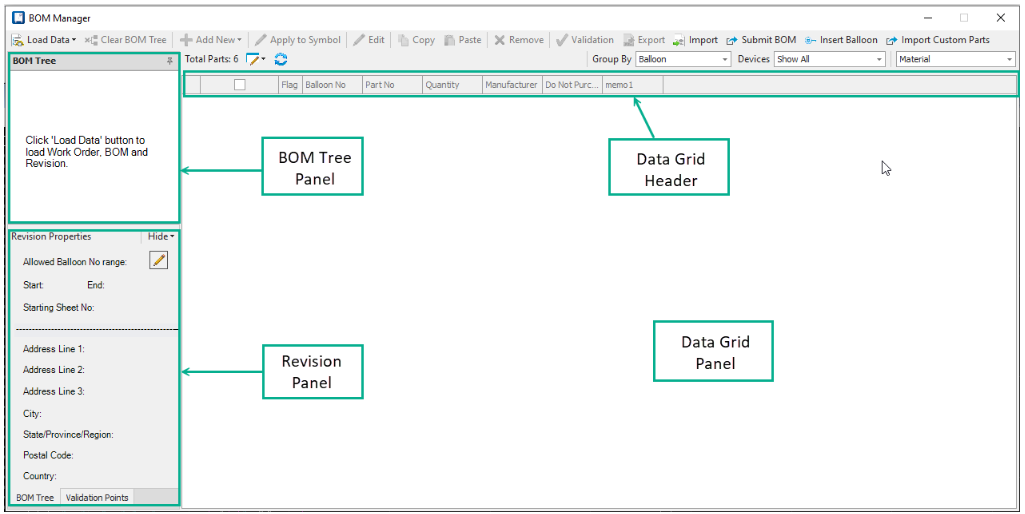
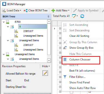
BOM Tree
 : Click the node to list the
parts/devices associated with the Work Order.
: Click the node to list the
parts/devices associated with the Work Order.
 : Click the node to display the
parts/devices associated with the BOM document.
: Click the node to display the
parts/devices associated with the BOM document.
 : Click the node to list the
parts/devices associated with the Revision.
: Click the node to list the
parts/devices associated with the Revision.
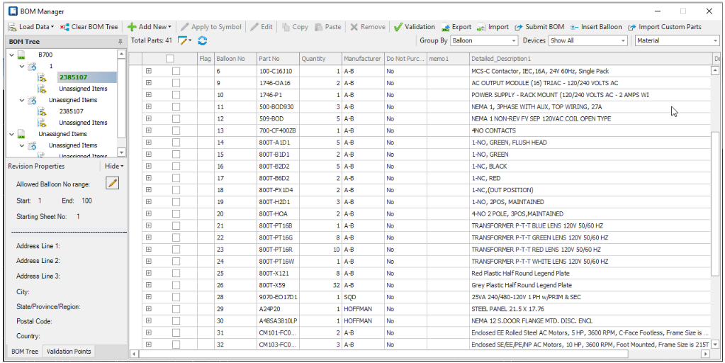
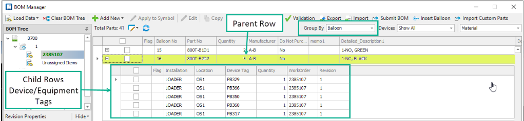
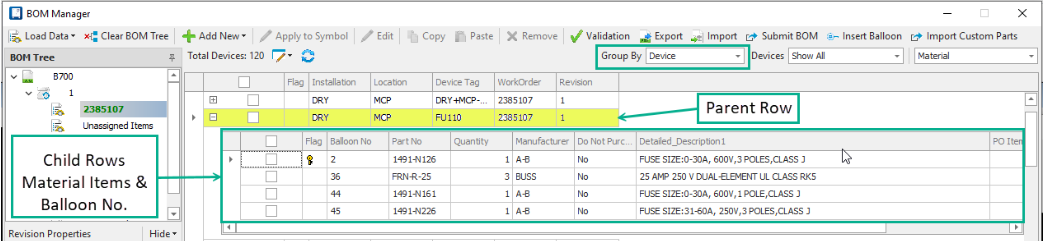
Selecting a node populates the data grid. Data shown in the grid depends on the node selected. For example, looking at the image below, data grid will show all items associated to BOM Document: HIGH BUS BOM.

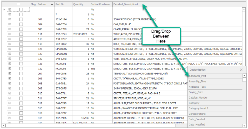
Data Grid Header (Column Chooser)
Column Chooser allows you to control the display of data within the data grid. You can add and remove desired data files or change the order of them in the data grid header.
- To access Column Chooser: Right-Click anywhere on data grid header. Select Column Chooser.
- Drag/Drop desired fields between Customization panel and data grid header. Hold left mouse button to drag, release left mouse button to drop. When finished, click X button in Customization panel. If you want to arrange the data grid columns in different order, change the field order Hold left button down on desired field. Move cursor to desired position and release left mouse button.
Group By Option
Group By setting provides two
methods to organize data within main data grid area. Clicking
 expands additional details
related to selected parent row.
expands additional details
related to selected parent row.
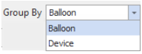
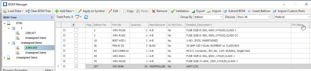
Example: Group By = Balloon
Example: Group By = Device
Moves Items between Nodes
Prior to moving Items, select desired records first using Check Boxes found in the data grid panel. Ctrl and Shift keys can be used for selecting multiple records. After desired records are selected, hold the left mouse button down on any one of the selected items, move cursor to destination node while holding left button, then release left button to complete.
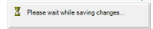
Example: Move items from Unassigned Items Revision Node to Revision Node 0.
Conditional Handling during Move process
Move Item dialog
Balloon numbers are associated with Part Numbers. Part numbers are associated with Devices (Equipment Tags). Word Order, BOM Document, and Revision attributes are also associated with Devices (Equipment Tags). Moving items from one node to another causes Word Order, BOM Document, and Revision attributes associated to Devices (Equipment Tags) to be updated with the destination node values. When a Device (Equipment Tag) contains multiple part numbers and multiple balloon numbers, the message below appears. Because Word Order, BOM Document, and Revision attributes are associated to Devices (Equipment Tags), all part numbers associated to the device must be moved together. Thus, the below message is asking you if you also want to move the additional part numbers associated to that Device (Equipment Tag).
Example:
- Device: CN257 contains 5 part numbers with the following:
- BOM Manager selection contains Balloon 207. Balloon numbers 419, 420, 421, 422 are not selected.
- Drag/Drop to move
Balloon 207 to destination node results in
below message.
Yes completes move. End result: All part numbers and balloon numbers associated to Device CN257 will appear under destination node.
No cancels move process. End result: All part numbers and balloon numbers associated to Device CN257 remain under source node.

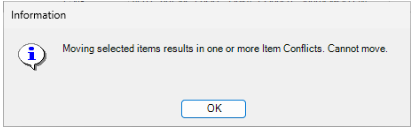
Item Conflict dialog
Unique Balloon Number required for each part number within a BOM Document. To prevent balloon number duplication, the software will display the message below when duplication is detected during move process.
Copy / Paste Items between Nodes
This function can be used to increase quantities or copy items. Prior to coping Items, select desired records first using Check Boxes found in the data grid panel. Ctrl and Shift keys can be used for selecting multiple records.
Copy /Paste functions can be accessed from top tool bar or right-click menu.
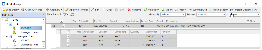
Example: Copy when destination node contains same balloon number and part number data.
Balloon No. 104 selected which includes 3 separate devices with quantity of 1. Parent row quantity is 3.
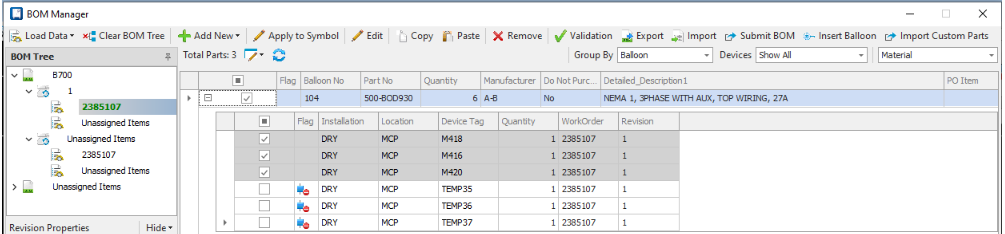
Result: After using Copy / Paste for Balloon No. 104.
3 Temp devices created (Temp35, Temp36, Temp37) and Parent row quantity update to 6.
Data Grid
The active BOM Tree node controls the display of records in the data grid. Only records matching selected BOM Tree node are displayed.
| Setting | Description |
|---|---|
| Flag Field |
|
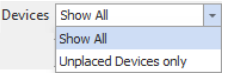
| Devices | Pull-down filter that controls data displayed. Selecting Unplaced Devices displays only records without an association to a placed symbol. |
| Views | Pull-down filter that controls the type of data displayed. You can change the default view of the data grid by selecting from the following options in the picklist: |
| Refresh | Select this button to refresh the information in the data grid. This could be useful in cases where multiple people may be collaborating in the same project. |
| Right-Click Functions | Right-Click in data grid opens
below menu containing following functions:
|
 Indicates Primary Part Number for
the Device. Applies when Group By option is set to Device.
Indicates Primary Part Number for
the Device. Applies when Group By option is set to Device.
 Indicates record does not have
associated symbol in model or drawing.
Indicates record does not have
associated symbol in model or drawing.

Revision Properties
When you select a revision node in the BOM Tree the Revision Properties panel will display the following information:
| Setting | Description |
|---|---|
| Allowed Balloon No Range | Displays the 'Start' and 'End' balloon range for the active BOM Document Revision. This is useful to ensure that when you are adding new entries to an existing BOM document that you do not accidentally reuse a previously taken balloon number. The BOM Manager will alert you if you attempt to enter a balloon number for a new part that is outside the specified range for this revision. Refer to Edit Revision Properties dialog to set a revision’s 'Start' and 'End' balloon values. |
| Starting Sheet No | Displays the starting page number of the bill of Material document that you want to add new entries to. This is useful if you have existing BOM documents and you want to add new items to the end of the existing document. You can define a BOM report template to use this starting number as the first page number of the report you generate. You could then merge the resulting report with your existing report to ensure that the page numbering flows properly. |
| Address | Optional fields which display the site address where the materials are to be shipped. |
| Edit Revision Properties | Select this button to display the Edit Revision Properties dialog dialog where you can edit properties for the selected revision. |
Toolbar Options
| Setting | Description |
|---|---|
| Load Data | Displays the Load Work Order(s) dialog letting you load the work order(s) which have been created for the project. |
| Clear BOM Tree | This option clears the items from the BOM Tree area of the dialog. Note the information is not deleted but simply removed from the tree. |
| Add New | This flyout button is context
sensitive and will enable or disable commands depending upon what you have set
focus to in the BOM Manager. The following commands are found here:
|
| Apply to Symbol |
Opens Apply to Symbol dialog. Use this function to quickly associate multiple part numbers to placed symbols. This is useful for assigning hardware items, such as bolts, nuts, washers, etc. to a selected group of terminal connectors. This feature is only enabled when one or more items are selected within the data grid. |
| Edit | You can select one or more part records and choose select Edit to display the Edit dialog. |
| Copy/Paste | Select the records you want to copy and click the Copy button to add the objects to the clipboard. Select the destination Work Order, BOM Document, and Revision in the BOM Tree and then choose the Paste button to copy the records. The device IDs will automatically increment to avoid duplication as required. |
| Remove | Select the records you want to remove and click the Remove button to effectively delete them from the project. You are not allowed, however, to remove devices that have symbols placed in the project. |
| Validation | You can perform various validation checks on the data in the BOM Manager for any given Work Order, BOM Document, and Revision to ensure that your data does not violate common design practices. Select this option to display the Validation dialog where you can toggle on the specific checks that are relevant to your organization to perform those validation checks. The checks are organized into categories making it convenient to toggle on or off all checks within a given category. |
| Export | Exports BOM data from active node selected in the BOM Tree to a .json file. |
| Import | Imports BOM Data from a .json file. |
| Submit BOM | Selecting this button displays
the
Submit BOM dialog letting you submit the BOMs for the
selected work order to a third-party purchasing system such as SAP.
By default, the software converts the BOM data into a JSON file which it then sends it to the specified URL. However, this functionality will need to be configured operate within the specifications of whatever system an organization uses to manage their work orders. |
| Insert Balloon | This option lets you insert
balloons for the selected devices into the drawing. Multiple devices can be
selected simultaneously and the balloons will be placed in order. If a device
has multiple instances in the drawing, you will be prompted to place a balloon
for each instance. Once all instances of one device have been placed, then the
balloon for the next device will be placed and continue until the balloons for
all selected devices are placed.
Because the balloons are associated with a device and not a specific symbol, you are able to place the balloons anywhere in the drawing. The balloons can be repositioned after placement if desired using the Move command. |
| Import Custom Parts | Opens Import Custom Parts dialog. User this function to import Non-Coded parts from a excel file. Non-Coded parts are items without an actual part number or stock code that you need to include on your bills of materials. Using this feature reduces Part Database maintenance by eliminating the need to create part numbers for non-stock items, such as, equipment structures built specific to the site. |